
First Contact — the Pogo prototype touches a board
We've written twice now about the DFT analyser — the web tool that reads your fab zip and tells you which nets are testable before you order boards. From the beginning we've described it as the software wedge that comes before a desktop tester. This post is about the tester.
It is not finished, it is not for sale, and — as we'll get to below — it isn't yet a flying probe. But it touches a real board, on purpose, in the right place, and tells you what it found. That felt worth showing.
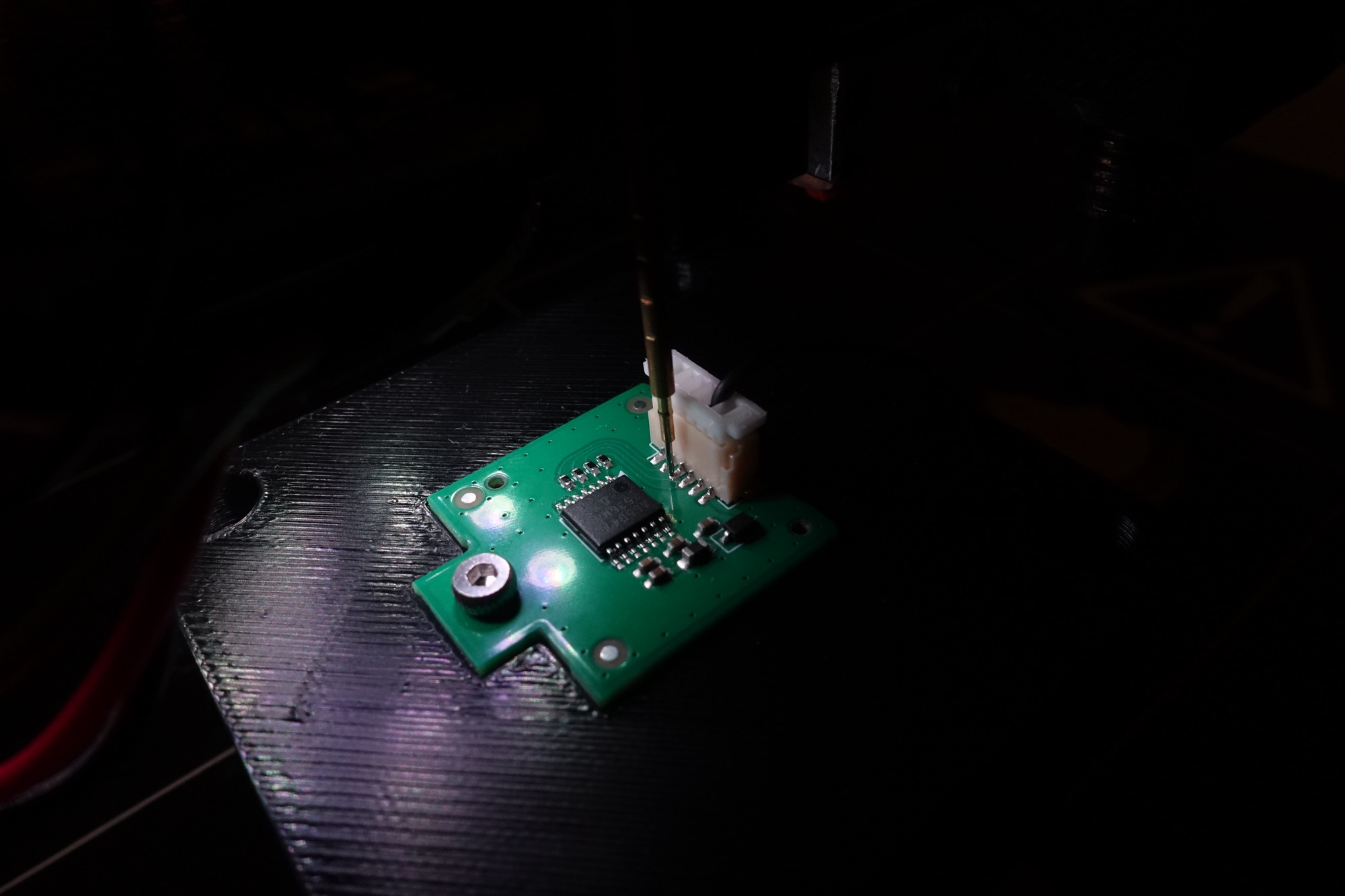
The moment the whole project is named after. That's a spring-loaded pogo pin on the end of a converted Prusa carriage, coming down on a pad it located from the board's fiducials.
What it actually is
Honesty first, because the photo flatters it. The Pogo prototype is:
- A Prusa i3 MK2 with the hotend removed, driven over USB by a small Python service that speaks Marlin G-code and exposes a WebSocket to the browser.
- A Raspberry Pi Pico 2 (RP2350) carrying a camera and a ring light, mounted so it looks straight down at the bed.
- A single spring-loaded pogo pin on the carriage, at a fixed offset from the camera axis.
- A resistor divider — 3.3 V through 47 kΩ to the Pico's ADC0, then 1 kΩ out to the probe tip. Clip a return lead to a net on the board and the divider tells you what the tip is touching.
That's the whole machine. There is no dedicated measurement IC, no second head, no tool changer. The "flying probe" is one pogo pin on a 3D printer carriage and a clip lead, and the interesting work is almost entirely in what the software does with those parts.
How a run goes
The choreography is the part we're proud of.
Teach. You home X and Y. Z can home too, but we've taken it off the everyday controls on purpose — a Z-home drives the head down toward the bed, and with a board clamped on it that's a crash, not a mistake you want one misclick away. Then you jog the camera to focus height and capture it. You park a reference point under the camera, capture, then under the tip, capture: the difference is the probe offset, and the tip's height is the touch depth. Finally you jog somewhere clear and set that as park.
Locate. You upload a plan CSV — probe points and fiducials in board-centre millimetres, straight out of the analyser — and jog each fiducial roughly into frame. A detector running in the browser auto-centres on it over a few passes, corrects to sub-pixel, and locks. Three or more fiducials fit board coordinates to machine coordinates, with the RMS error shown in millimetres so you can tell a good fit from a hopeful one. (There's a section on exactly how below.)
Probe. The tour orders the points with a 2-opt pass so the head isn't crossing the board twice for neighbouring pads, then for each one: move the tip over the pad, fast-approach to 1 mm above the taught depth, plunge the last millimetre at 60 mm/min, and measure for five seconds. Lift 3 mm. Next pad.
Judge. Two verdicts, and a row has to pass both. The netlist check asks whether contact matches expectation — this pad should read as connected to the reference net, or it shouldn't — and votes over the settled window. The band check is optional: upload a CSV of net,min,max and each reading is checked against its own limits.
Park and re-check. The tour ends at the park position. The only path back onto the board re-measures every fiducial, and if the board has drifted more than 1.5 mm it refuses to re-fit rather than driving a pin onto stale coordinates. That threshold isn't arbitrary — past roughly 1.5 mm the detector can confidently lock onto the neighbouring feature, which is a far worse failure than stopping.
Seeing the board
The two hard problems on a machine like this are where is the board and where is the pad — and the camera answers both before a single axis moves toward a probe.
Calibration comes first, and it's the load-bearing number. The camera has to know how many millimetres a pixel is worth, because every jog and every plunge is computed from what it sees. So you point it at a printed ChArUco board — a chequerboard salted with ArUco markers — and press calibrate. A small Rust module compiled to WebAssembly runs right there in the browser: it finds the chequerboard corners, fits a homography from the board's known square size onto the image, and reads off millimetres-per-pixel along with the in-plane rotation and an RMS error in pixels, so you can see how well it fit. On a clean capture that's around 0.6 px over 59 corners.
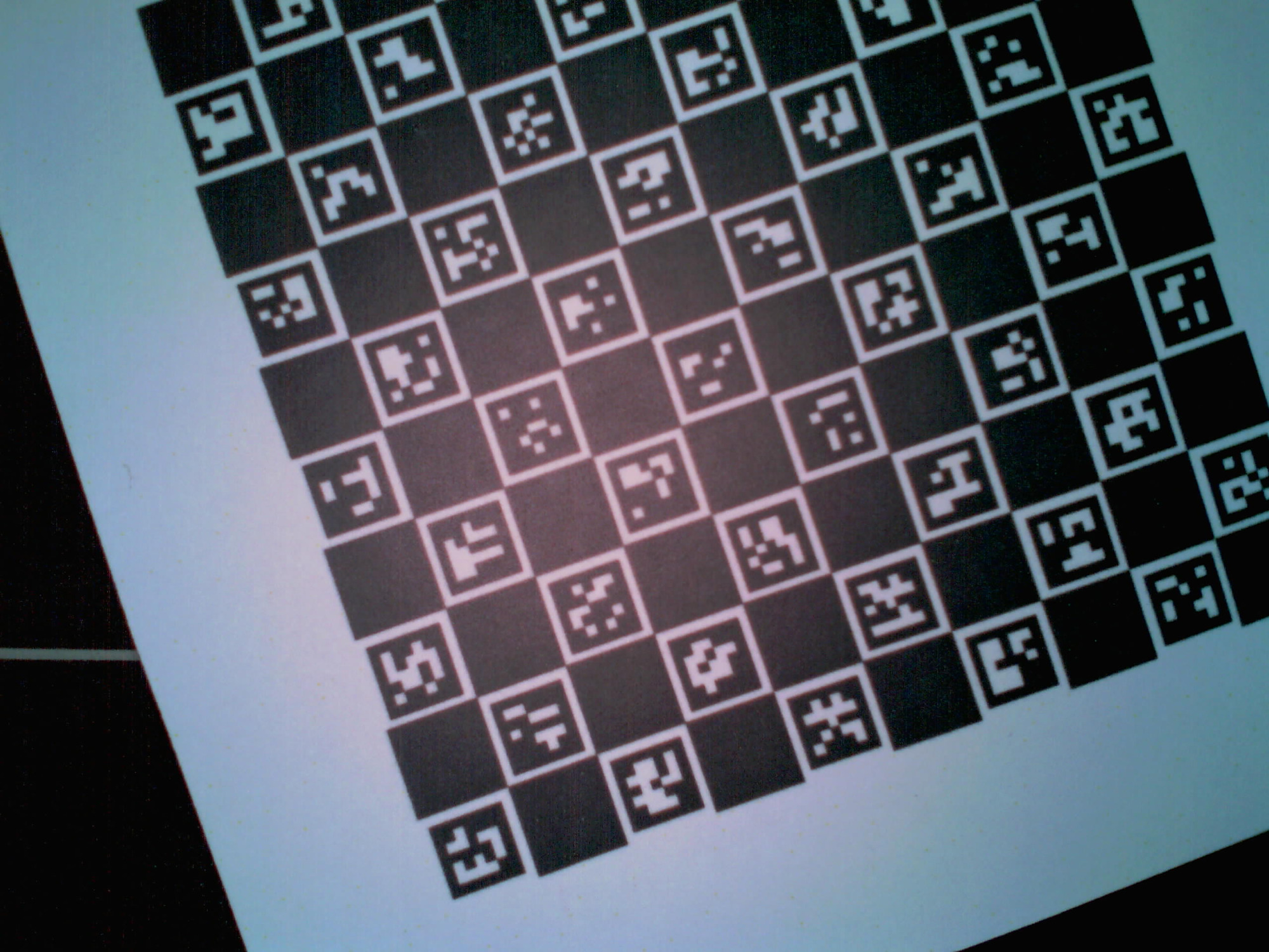
The camera learns its scale from a printed ChArUco target. The physical edge of one square — 5 mm — is the single source of truth: get that number wrong and every move the machine makes scales by the same ratio.
Two details keep this honest. The scale is calibrated at the PCB surface height, so millimetres-per-pixel is exact at the working distance the probe actually operates at, not at some other focal plane. And the frame's true width is derived from that calibration rather than measured separately — which is only valid because the camera's resolution presets share one field of view (they scale, not crop). There's also an optional radial-lens correction — a two-coefficient Brown–Conrady model fit from the same target — that pulls the barrel distortion out of the frame so a fiducial near the edge sits where the maths expects. It's off by default; near the centre, where the tour keeps its work, it barely matters.
Then the fiducials. You jog each one roughly into frame and the detector takes over. It doesn't threshold on colour or brightness — it scores circular symmetry, the one thing every round fiducial has and almost nothing else on the board does, working entirely on a greyscale frame so a bare gold pad and a green-masked one read the same. Seeded at the centre of the frame it locks on to sub-pixel accuracy, then the head auto-centres over up to five passes: detect, jog the offset out, settle, re-detect — until the fiducial is dead-centre (within about a quarter of a millimetre) or the passes stop improving. Centring is deliberate: it's where lens distortion is lowest, so the machine coordinate at the moment of lock is the fiducial's true position.
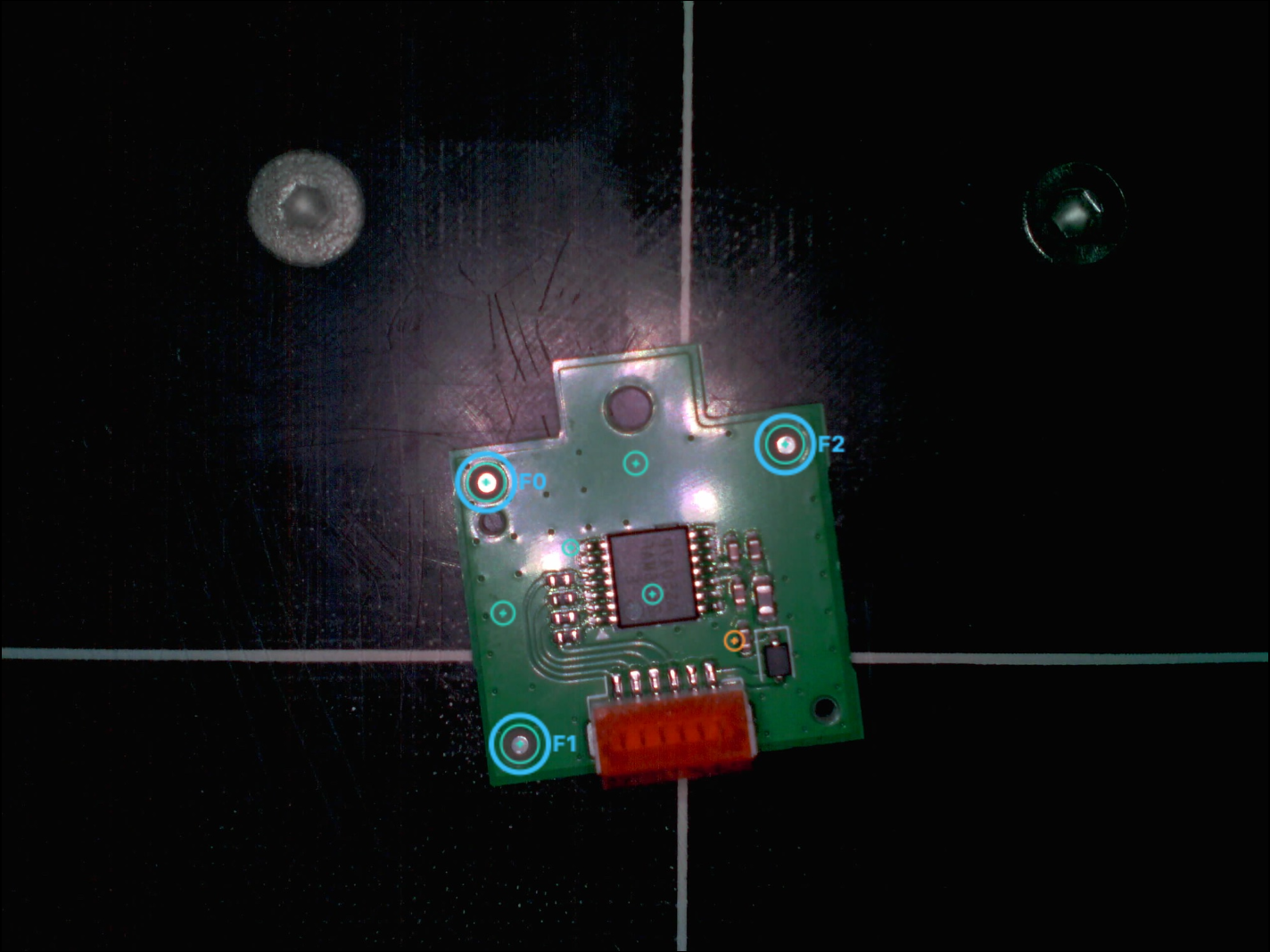
Three fiducials located and locked (F0–F2, in cyan), with the plan's probe points ringed in teal. The white cross is the machine origin; the amber ring is a lower-confidence detection still waiting for a manual lock.
Three of them make a map. Each locked fiducial pairs a board coordinate (from the plan) with a machine coordinate (where the head actually was). Three or more of those pairs are fit to a 2-D similarity — rotation, uniform scale, translation, and a reflection if the board is flipped — deliberately not a full affine, because a rigid board held in a nest can't shear or stretch, and allowing it to would just be fitting noise into the transform. The fit is closed-form and order-independent: lock the fiducials in whatever order you like and it tries every pairing, keeping the one whose residual is smallest, because a wrong correspondence blows the error up unmistakably. That residual, in millimetres, sits next to the result — a good board lands well under a tenth of a millimetre — and it's the same number the end-of-run re-check leans on to decide whether the board has drifted too far to trust.
What it isn't
We should be blunt about this, because the words are load-bearing in this industry.
A real flying-probe tester — SPEA's 4060 is the machine most people picture — has multiple independently-driven heads working both sides of the board, testing arbitrary net-to-net pairs, with real measurement hardware behind each probe. Our prototype has one pin. It only reaches the top side — the tour silently skips bottom-side probes. And its entire test model is "is this pad connected to the one net I clipped a wire to?" There is no net-to-net matrix, no isolation testing, no second probe to make one possible.
It's also a go/no-go continuity check with a resistance readout, not a precision ohmmeter. Near a grounded net, quantisation alone is about 12 Ω per ADC count; there's no four-wire sensing, no current source, and nothing that calibrates against a known standard. When it says 20 Ω, believe the "connected", not the "20".
The rest of the honest list: every taught value lives in the browser's local storage as a session-relative machine coordinate, so a power cycle or a re-home invalidates all of it. Two Python processes and a browser tab, all on localhost, all started by hand. And the machine and the web analyser are not one system — the plan CSV is exported from one and uploaded into the other by a human.
So: a working single-board lab prototype. The gap between this and the thing in our own product description is exactly the gap we're now working on.
What's next
Two heads is the obvious one, and the one that turns "continuity to a clip lead" into real net-to-net testing. Before that, though, there's less glamorous work that matters more: a persistent Z datum so teaching survives a power cycle, and closing the loop between the analyser and the machine so a plan flows from Gerbers to pads without a human in the middle.
If you run a fixture house or a prototype lab and any of this sounds like it's heading somewhere useful — or somewhere obviously wrong — we'd genuinely like to hear it. Write to hello@pogorobotics.io. Real boards are still the only benchmark that counts.
The probes come to the board. Slowly, one at a time, on the top side only — but they come.