
Height reconstruction from a fixed-distance camera on a moving stage
A flying probe needs some idea of how tall things are, so it can approach a pad without striking what surrounds it. This post describes an experiment: whether the camera already on the machine for fiducial location can also give us height, with no extra sensor and no motion the machine does not already perform.
It can, on the board we tried it on. What follows is that one experiment — the geometry it rests on, the numbers it produced, and the two error sources that account for most of what is still wrong. Everything here comes from a single assembly, so read the figures as observations rather than as performance we are claiming.
Why the camera is there in the first place
The camera exists to solve a two-dimensional problem. Fiducials — small bare-copper circles at known positions in the design — are located optically, and fitting them against their design coordinates gives the transform from board millimetres to machine millimetres, so a probe point specified in the layout can be reached on the bench.
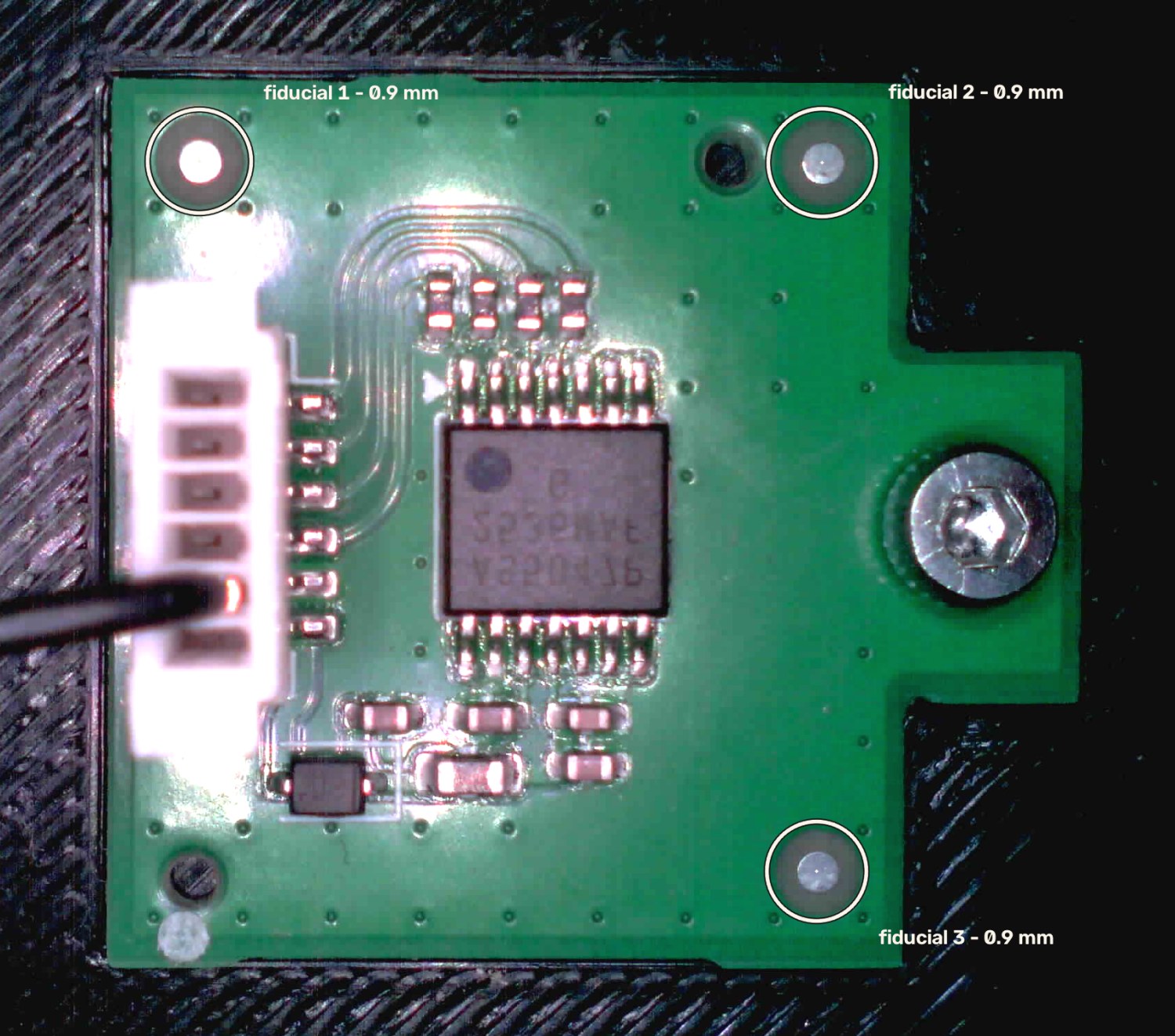
A single frame from the run described below, at the working distance the scan uses. The three ringed features are the board's fiducials, found here by circular-symmetry detection; each measures about 0.9 mm across at the calibrated scale of 15.6 µm per pixel. The previous post covers how their positions fix the board-to-machine transform.
Height is the other half of the problem, and the constraint is that the camera is bolted to the carriage at a fixed standoff. It cannot move along its optical axis, so there is no focus sweep, and there is no second camera for stereo. The only freedom is the two lateral stage axes.
The geometry
Sliding the camera sideways over a scene with relief produces differential parallax. For a working distance z₀ and a lateral baseline t, a surface at height z above the reference plane shifts between two views by
Δ(z) = t · z₀ / (z₀ − z)so the difference in shift between the board plane and something standing above it carries the height. The stage reports t directly, which is what makes the result metric without calibrating scale against anything else.
The magnitudes are small. At a working distance near 40 mm and a 2.5 mm baseline, a board-level pad moves about 160 px between adjacent views and a 1 mm component top about 164 px. The whole method is an inference over that ~4 px difference, repeated per pixel.
How a run works
Forty frames are captured on a fixed-Z serpentine grid with 93.75% overlap, at one working distance, with illumination and exposure held constant. Frames are registered pairwise by phase correlation; the stage's commanded moves constrain the global fit, and pairs whose measured shift disagrees with it are dropped.
Height then comes from a plane sweep: for each pixel of a reference frame, a set of candidate heights is tried by warping the neighbouring frames according to the expression above and scoring agreement by zero-mean normalised cross-correlation. The best-agreeing height is kept, subject to the two rejections below. Estimates from several reference frames are fused onto a common raster.
Two things that go wrong
Neither of these averages away, which is what makes them worth describing.
Highlights that move faster than the surface
The ring light is mounted on the camera, so a specular highlight is not a property of the surface. On a curved feature it slides as the camera slides, and it slides faster than the surface beneath it. Since shift is read as height, that extra motion is reported as extra height, and the estimate climbs until the warp runs out of support — around 12 mm on this geometry.
These are not identifiable by brightness. Masking near-saturated pixels reaches under 2% of the affected cells, because the offending highlights are mid-tone rather than clipped. The pipeline's own confidence measure does not help either: it describes how sharply the cost minimum peaked, and a specular match peaks sharply.
What does separate them is a null hypothesis. Evaluating the degenerate "camera-fixed" layer — comparing frames with no warp at all — gives a baseline that a real surface beats by a wide margin and a spurious one does not. Over the pixels of one reference frame, the margin by which the best height beat that baseline was around 0.52 (ZNCC) on the board plane and around 0.005 on the affected population. The latter is, in effect, indifferent between a surface 10 mm up and no surface at all.
Estimates with nothing to agree with
Where the window carries no gradient, there is no true minimum and the estimate settles on a noise feature. These are stable if you measure again, so repetition does not remove them.
The intuitive filter — drop an estimate that sits far from its neighbours' average height — turns out to be a bad idea, because a step edge is legitimately far from its neighbourhood. Component flanks, connector walls and cable edges all qualify. Tuned to remove a given quantity of speckle, it also removed a little over half of a cable that is plainly visible in the photographs.
Counting agreeing neighbours instead asks a different question, and separates the two cases: an estimate on a real edge still has a half-neighbourhood at its own height, while an isolated speckle has none. At the same speckle removal the cable kept about 98% of its cells, and the height step across the connector's contour came out larger rather than smaller — the boundary got crisper, what sat just outside it having been spurious.
What came out
Below is the result on that board, with both rejections applied. Colour is height by default; the photographic texture is there for orientation.
Loading point cloud…
Over the ±0.3 mm band around the fitted plane, the board surface came out to about 161 µm (1σ) — a repeatability figure for this raster, not an accuracy figure against a standard. The wire-to-board connector, which we measured at 7 mm with calipers, came out at 6.53 mm, and its cable resolves as a continuous raised structure. Three estimates land above 10 mm, where nothing on this board exists; before the two rejections there were 1,130.
Acquisition is 40 frames and reconstruction takes minutes on a laptop, with working resolution traded against runtime.
What we do not know yet
The connector reads 0.47 mm below its caliper height and we have not established why. One candidate is geometric rather than algorithmic: at a 40 mm working distance a 7 mm feature is 18% of the way to the entrance pupil, so its top and the board plane cannot both be in focus, and the raised surface is correlated through some defocus. If that is the dominant term the answer is capturing at more than one focus setting, not a cleverer estimator — but we have not run the experiment that would separate it from the alternatives.
More generally: one board, one operator, one fixture. The numbers above are what this run produced, not a specification, and we would expect them to move on a board with different finish, component mix or soldermask.
Why it is worth pursuing
A probe that knows the height field can plan around it — approach a pad without clipping the connector beside it, or flag that two probes cannot both reach. That is the same conversation the testability analysis already has with you about which nets are reachable, extended into the third dimension.
And it needs no new hardware. The camera was there for fiducials, the motion was there for probing, and the ruler is the machine itself.